
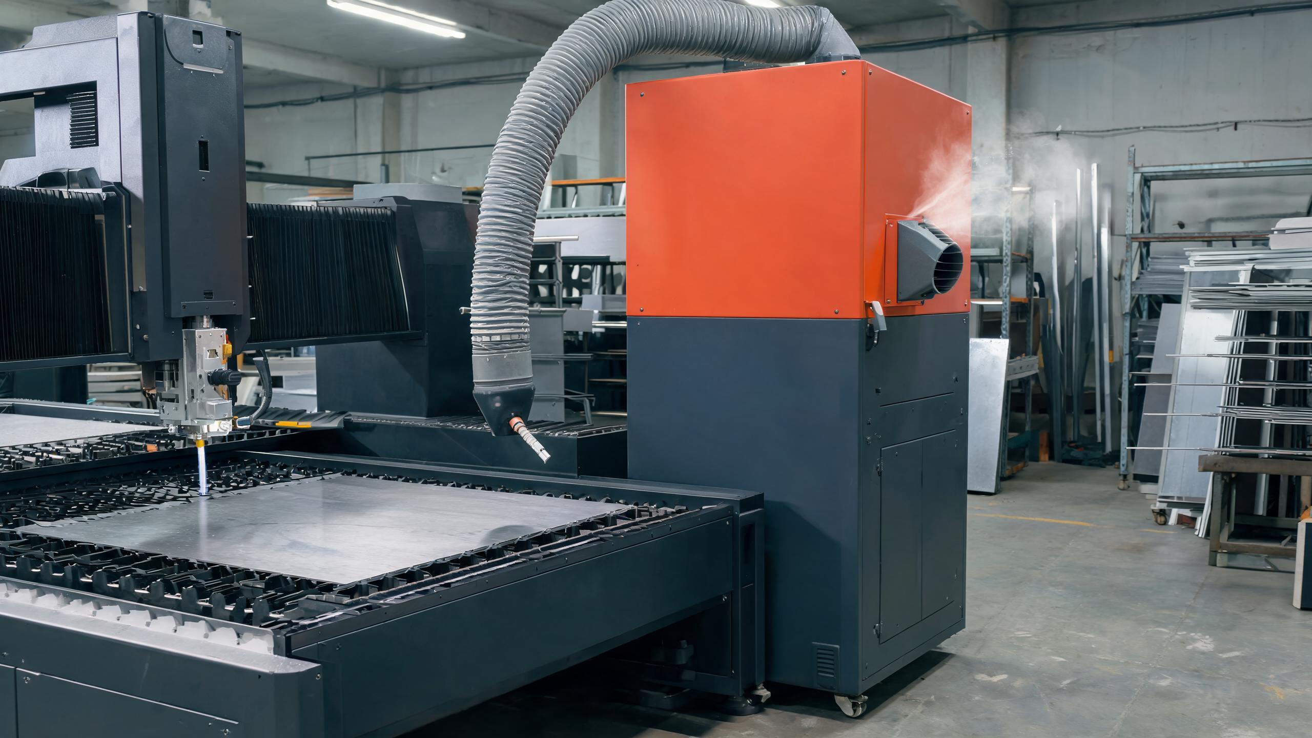
Learn the practical steps to set work offsets and tool offsets on a CNC machine, avoid common mistakes, and understand how laser cutting offsets differ. A clear guide for CNC operators and buyers.
CNC OPERATOR GUIDE
If you are new to CNC machining or need a refresher, setting offsets correctly is the difference between a good part and a scrapped one. Offsets tell the machine where the part is and where the tool tip is. Get them wrong, and you may cut air, crash the spindle, or produce parts out of tolerance.
This guide covers the two main types of offsets—work offsets and tool offsets—with step-by-step setup instructions, common mistakes, and a section on how laser cutting offset differs from milling or turning.
What Is an Offset in CNC Machining?
An offset is a stored coordinate value that the CNC control uses to align the machine's coordinate system with the actual part and tool. Without offsets, the machine would not know where the part is on the table or how long each tool is.
There are two categories:
- Work offsets – define the origin (zero point) of the part on the machine table.
- Tool offsets – define the length and diameter of each cutting tool.
Both are stored in the controller and can be adjusted individually. Most modern CNC controls (Fanuc, Siemens, Haas, Mitsubishi) follow the same logic, though the exact button labels may differ.
How to Set Work Offsets
Work offsets (often G54–G59) tell the machine where the part's zero point is. The most common method is the edge finder or touch probe method.
Step-by-Step Procedure
- Mount the workpiece securely on the table or in a vise.
- Select the work offset – e.g., G54 for the first part, G55 for the second, and so on.
- Use an edge finder or probe to locate the X and Y edges of the part. Move the tool slowly until it touches the edge, then zero the relative position.
- Enter the values into the work offset page. For example, if the edge finder is 10 mm in diameter, you must add half the diameter to the coordinate to get the true edge.
- Set the Z zero – use a tool setter or a piece of paper to find the top of the part. Enter this value as the Z offset.
- Verify by running a test cut or using the machine's "dry run" mode.
How to Set Tool Offsets
Tool offsets compensate for the different lengths and diameters of tools. When you change a tool, the machine needs to know how long it is relative to the spindle nose or gauge line.
Tool Length Offset
- Place the tool in the spindle.
- Use a tool presetter or a manual method: lower the tool until it touches a fixed surface (like the top of a 10 mm gauge block).
- Record the Z position in the tool offset page (e.g., offset #1 for tool 1).
- Repeat for each tool in the program.
Tool Diameter Offset (Cutter Compensation)
For milling, the tool diameter offset (D value) is used for cutter radius compensation. This is typically the actual diameter of the tool, measured or taken from the tool catalog. It allows the machine to adjust the tool path to account for tool wear or deflection.
| Offset Type | Purpose | Typical Values |
|---|---|---|
| Work offset (G54) | Part origin X, Y, Z | Coordinates in mm or inches |
| Tool length offset (H) | Tool length compensation | Length in mm or inches |
| Tool diameter offset (D) | Cutter radius compensation | Diameter in mm or inches |
Laser Cutting Offset: What's Different?
Laser cutting machines also use offsets, but the concept is different from mechanical machining. In laser cutting, the offset refers to the beam compensation or kerf width—the width of material removed by the laser beam.
When you program a laser cutter, you must input the kerf offset so the machine can adjust the cut path. If the offset is too small, parts may be oversized; if too large, parts may be undersized. The correct value depends on the material type, thickness, and laser power.
For example, cutting 2 mm mild steel with a 1.5 kW fiber laser may require a kerf offset of around 0.2–0.3 mm, but this varies by machine and settings. Always run a test cut to calibrate.
Common Mistakes and How to Avoid Them
- Using the wrong work offset – Always double-check that you are editing the correct G-code (G54 vs. G55).
- Forgetting to add tool radius – When using an edge finder, you must add half its diameter to get the true edge.
- Not updating tool offsets after tool wear – Regularly measure tool length and diameter, especially for long runs.
- Setting Z zero incorrectly – Use a consistent reference, like the top of the part or a fixed gauge block.
- Ignoring thermal expansion – On long runs, the machine and part may expand. Re-check offsets periodically.
Verifying Offsets Before Production
Always run a test piece before full production. Use the machine's single-block mode and dry run to check the tool path without cutting. This helps catch offset errors before they ruin a part or damage the machine.
If you are buying a CNC machine, ask the supplier for the offset setting procedure and whether they provide training. A good supplier will offer documentation and technical support to help you set up offsets correctly.
Frequently Asked Questions
What is the difference between G54 and G92?
G54 is a work offset stored in the machine's memory. G92 is a temporary shift of the coordinate system within the program. G54 is more common for production because it is easier to manage.
Can I use the same tool offset for different tools?
No, each tool must have its own offset. Using the same offset for different tools will cause incorrect depth cuts and potential crashes.
How often should I check offsets?
Check offsets at the start of each shift and after any tool change or part repositioning. For high-precision work, check more frequently.
Final Advice for CNC Buyers and Operators
Setting offsets is a fundamental skill that directly affects part quality and machine safety. Whether you are running a 3-axis mill, a lathe, or a laser cutter, the principles are the same: know your reference points, measure accurately, and verify before cutting.
If you are sourcing a CNC machine, ask the supplier about the control system and whether they offer training on offset setup. A reliable supplier will be transparent about the machine's capabilities and provide clear documentation.
Need help choosing a CNC machine or laser cutter for your workshop? Contact us to discuss your requirements—we can recommend a machine that fits your production needs and budget.