
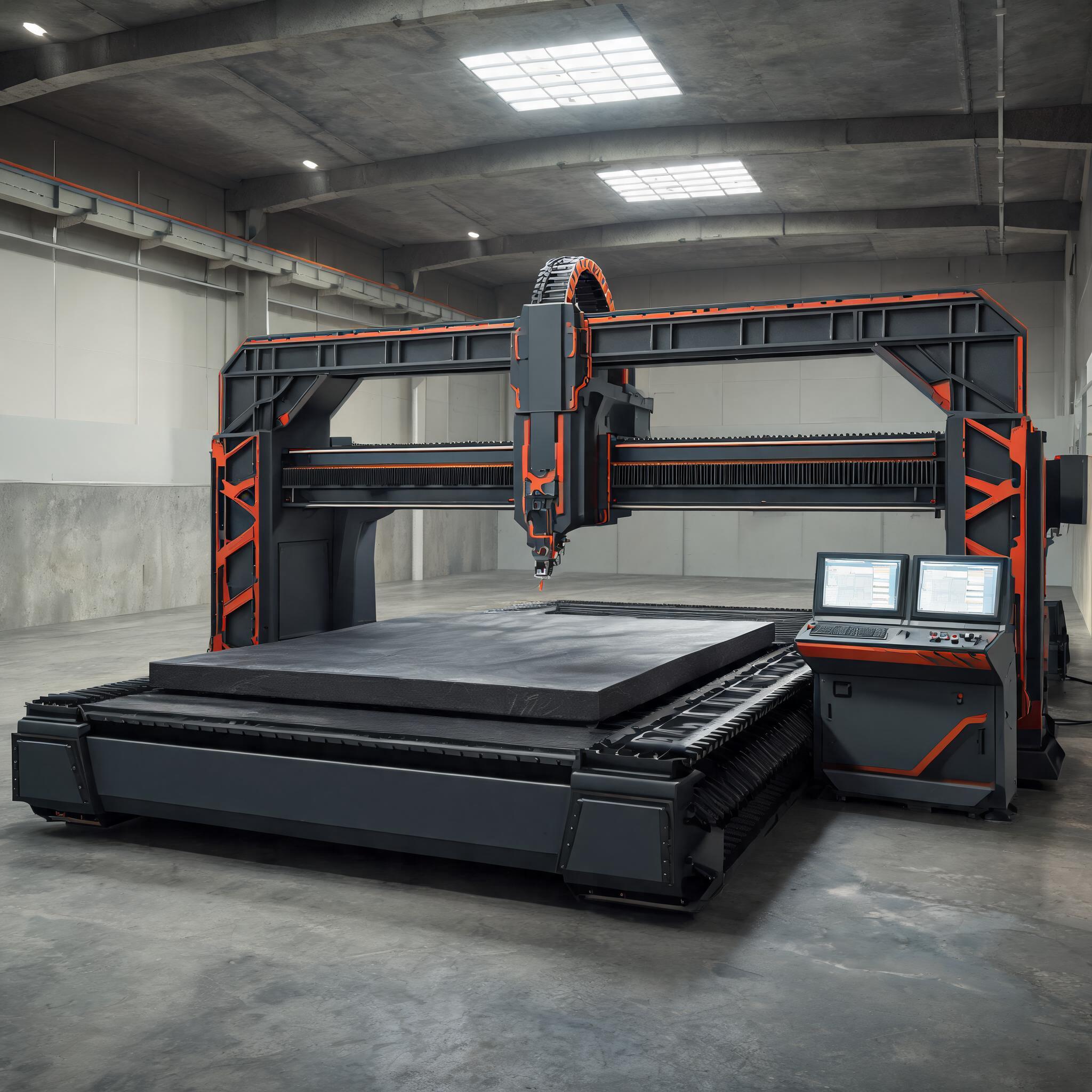
Learn the complete CNC milling machine setup process—from machine cleaning and tooling to workholding and test runs—and compare CNC milling with laser cutting for material, precision, and production scenarios.
MACHINE SETUP GUIDE
Setting up a CNC milling machine correctly is the difference between a part that meets tolerance on the first run and a scrapped workpiece, a broken tool, or a damaged spindle. For machine shops and manufacturers sourcing parts or adding capacity, a repeatable setup procedure also reduces downtime and keeps quality consistent across batches. This guide walks through the essential steps of CNC milling machine setup, then compares CNC milling with laser cutting so you can choose the right process for your material and production needs.
- A proper CNC milling setup follows a fixed sequence: clean, inspect, tool, set work offsets, dry-run, then cut.
- Workholding and tool runout are the two most common sources of setup error—check both before the first cut.
- CNC milling removes material with rotating cutting tools; laser cutting uses a focused beam. Choose based on material, thickness, tolerance, and production volume.
- Milling suits metals, 3D shapes, and tight tolerances; laser cutting excels on thin sheets and complex 2D profiles, especially in plastics and mild steel.
What Is CNC Milling Machine Setup?
CNC milling machine setup means preparing the machine, tooling, workholding, and program so that a machining operation runs correctly and safely. It includes mechanical checks, tool selection and measurement, workpiece clamping, coordinate system setting, and a trial run before actual cutting. A structured setup procedure is essential for both job shops and production lines—it minimizes scrap, protects the machine, and ensures repeatable part quality.
Step-by-Step CNC Milling Machine Setup
Follow these steps in order. Skipping one—especially cleaning or dry-running—often leads to errors that are expensive to fix.
1. Clean the Machine and Work Area
Start with a clean machine. Remove chips, coolant residue, and debris from the table, spindle taper, and tool holders. Wipe the workholding surfaces. A dirty taper can cause tool runout; chips under a vise or fixture change the workpiece position. Clean the machine before every setup, not just at the end of a shift.
2. Inspect the Machine and Safety Systems
Check the spindle for abnormal noise, verify that the coolant system is filled and functioning, and confirm that the emergency stop and door interlocks work. Inspect the tool changer (if equipped) and the way covers. Any issue found here should be fixed before loading tools or workpieces.
3. Select and Load Tools
Choose the correct tools for the operation: end mills, drills, taps, or inserts. Load each tool into a holder and set the tool length offset. Measure the tool length precisely—either with an automatic tool presetter or a manual height gauge—and enter the values into the CNC control. Incorrect tool length offsets are a leading cause of crashes and depth errors.
4. Set Up Workholding
Mount the vise, fixture, or clamping system onto the machine table. Indicate the workholding to ensure it is square and parallel to the machine axes. For vises, clean the jaws and the workpiece surfaces. For fixtures, verify that locating pins and clamps are secure. The workpiece must be rigid—any movement during cutting will ruin the part and can break the tool.
5. Set Work and Tool Offsets
Establish the workpiece coordinate system (G54, G55, etc.) by touching off on the workpiece edges or using an edge finder. Set the X and Y zero at the desired reference point (usually a corner or the center of a hole). Set Z zero at the top of the workpiece. Record these offsets in the control. If using multiple work offsets, verify each one against the program.
6. Load and Verify the Program
Transfer the CNC program to the machine control. Review the program for errors: correct tool numbers, feed rates, spindle speeds, and coordinate system calls. Check that the program matches the workpiece orientation and the work offset you set. Many shops use CAM simulation software to verify toolpaths before running on the machine—this is strongly recommended for complex parts.
7. Dry-Run and Test
Run the program with no workpiece (or with the spindle off and the tool retracted) to check for collisions, rapid moves, and correct toolpath. Use single-block mode to step through the program. Then, if possible, run a test cut on a scrap piece of the same material. Measure the test part against the drawing. Adjust offsets if needed.
8. Run the First Part and Inspect
Once the dry-run and test are successful, load the actual workpiece and run the program. Monitor the first part closely—listen for unusual sounds, watch for excessive vibration, and check chip formation. After the part finishes, measure critical dimensions with calipers, micrometers, or a CMM. Document the results. If the part is within tolerance, the setup is complete and you can proceed with the batch.
- Not cleaning the taper or spindle—causes tool runout and poor surface finish.
- Setting work offsets without verifying the workpiece is square—leads to angled features.
- Skipping the dry-run—risks a crash that damages the machine or tool.
- Using incorrect tool length offsets—can cause the tool to plunge too deep or miss the part entirely.
- Ignoring workholding rigidity—a loose part moves during cutting, ruining accuracy.
CNC Milling vs. Laser Cutting: How They Compare
CNC milling and laser cutting are both subtractive manufacturing processes, but they work in fundamentally different ways. Milling uses a rotating cutting tool to physically remove material; laser cutting uses a focused high-energy beam to melt, burn, or vaporize material along a path. The right choice depends on your material, part geometry, tolerance, and production volume.
| Factor | CNC Milling | Laser Cutting |
|---|---|---|
| Process | Rotating cutting tool removes material mechanically | Focused laser beam melts/vaporizes material |
| Materials | Metals (aluminum, steel, titanium), plastics, wood, composites | Sheet metal (mild steel, stainless, aluminum), plastics, wood, acrylic |
| Thickness | Works on thick blocks and 3D shapes | Best for thin sheets (typically up to ~20-25 mm mild steel) |
| Geometry | 3D contours, pockets, holes, threads, complex features | 2D profiles, intricate cutouts, fine details |
| Tolerance | Tight, often ±0.025 mm or better | Good, typically ±0.1-0.2 mm depending on material |
| Edge quality | Good surface finish, may need deburring | Clean, square edges; heat-affected zone on some materials |
| Tooling | End mills, drills, taps—wear over time | No physical tool wear; focus lens and nozzle maintenance |
| Setup complexity | Requires tooling, workholding, offsets | Requires focus, nozzle, gas pressure settings |
| Production volume | Ideal for low to medium volumes, complex parts | Ideal for high-volume 2D cutting of thin sheets |
| Cost per part | Higher for simple 2D cuts, lower for complex 3D | Lower for simple 2D cuts, higher for thick materials |
When to Choose CNC Milling
Choose CNC milling when you need:
- 3D features like pockets, slots, bosses, and threads.
- Parts from solid blocks or thick plates.
- Tight tolerances (e.g., ±0.025 mm) and good surface finish.
- Materials that are difficult to laser cut, such as thick aluminum or titanium.
- Low to medium production runs where tooling cost is justified.
When to Choose Laser Cutting
Choose laser cutting when you need:
- Intricate 2D profiles in sheet metal or plastic.
- High-speed cutting of thin materials (e.g., <6 mm mild steel).
- Narrow kerf and minimal material waste.
- No mechanical tooling changes between different shapes.
- High-volume production of identical flat parts.
"For a machined part with a tapped hole and a 0.05 mm flatness requirement, CNC milling is the standard. For a decorative acrylic sign with fine lettering, laser cutting is faster and cleaner."
Choosing Between Milling and Laser for Your Project
If your part is a flat profile with simple holes and you need high volume, laser cutting is often more economical. If your part has depth, threads, or tight tolerances, CNC milling is the right process. Some shops use both: laser for cutting blanks, then milling for finishing features. Discuss your part drawings with your supplier to determine the most efficient method.
FAQs on CNC Milling Setup and Process Comparison
How long does a typical CNC milling setup take?
Setup time varies widely. A simple vise setup with one tool might take 15–30 minutes; a complex fixture with multiple tools and offsets can take several hours. Skilled operators and tool presetters reduce this time.
What is the most critical step in CNC milling setup?
Setting the work offset correctly. If X, Y, or Z zero is wrong, every feature on the part will be shifted. Always verify offsets with a test cut or by measuring the first part.
Can laser cutting achieve the same tolerance as CNC milling?
Generally no. Laser cutting typically holds ±0.1–0.2 mm, while CNC milling can hold ±0.025 mm or better. For press-fit or mating parts, milling is usually required.
Is laser cutting faster than CNC milling?
For thin sheet metal, laser cutting is often faster because it cuts the entire contour in one pass. Milling may require multiple passes and tool changes. For thick materials, laser cutting speed drops significantly.
Conclusion
A disciplined CNC milling machine setup—clean, inspect, tool, workhold, offset, dry-run, and test—ensures accurate parts and protects your equipment. When deciding between CNC milling and laser cutting, evaluate the material, thickness, required tolerance, and production volume. Milling excels at 3D metal parts with tight tolerances; laser cutting wins for fast, intricate 2D profiles in thin sheets. For your next project, share your drawings and specifications with a qualified machining supplier to get a process recommendation and a quote that fits your needs.