
Learn how to set up a CNC machine correctly, from site preparation and power checks to tool setup and test runs. This guide also covers laser cutting machine setup, common mistakes, and a pre-start checklist for B2B buyers and operators.
BUYER & OPERATOR GUIDE
Setting up a CNC machine correctly is the difference between a first part that passes inspection and a costly crash that damages the spindle, the workpiece, or the tooling. Whether you are installing a 3-axis milling center, a CNC lathe, or a laser cutting machine, the core steps are similar: prepare the site, connect utilities, level the machine, verify safety systems, load the program, and run a careful test.
This guide walks through the full CNC machine setup process in a logical order, with a dedicated section for laser cutting machine setup. It is written for shop owners, production managers, and maintenance leads who need a practical checklist—not a theoretical overview.
- Site preparation (floor flatness, clearance, power) prevents most installation problems.
- Leveling and anchoring are mandatory for accuracy and machine longevity.
- Verify electrical supply, air pressure, and coolant before first power-on.
- Always run a dry test and a test part before production.
- Laser cutting machines require extra attention to optics, exhaust, and gas supply.
Before You Start: What You Need for CNC Machine Setup
Proper setup starts before the machine arrives. Check the following items against the manufacturer's manual—these specifications vary by machine model, so always confirm with your supplier.
- Floor load capacity: A typical CNC milling machine can weigh 2,000–10,000 kg. Verify the concrete floor can support the machine's footprint plus dynamic loads.
- Clearance: Allow at least 1 meter around the machine for maintenance, chip removal, and safe operator movement. For laser machines, also plan for exhaust ducting and gas cylinder storage.
- Power supply: Check voltage (e.g., 220V or 380V), phase (single or three), and total amperage. Most industrial CNC machines require three-phase power. Confirm the breaker rating and install a dedicated circuit.
- Compressed air: Many CNC machines use air for tool changers, clamps, or cleaning. Check required pressure (often 6–8 bar) and flow rate. Install a filter-regulator-lubricator (FRL) unit if not included.
- Coolant system: For milling and turning, ensure a coolant tank, pump, and proper disposal or recycling system are ready.
If you are unsure about any of these, ask the supplier for a site preparation drawing or checklist. Most reputable manufacturers provide one.
Step 1: Unpacking and Positioning
Move the machine into place using a forklift or crane rated for the machine's weight. Follow the lifting points marked on the crate or machine body—never lift from the table, spindle, or covers.
Place the machine on the floor, leaving enough space for the control cabinet door to open fully and for chip conveyors to operate. For laser cutting machines, position the machine so the exhaust outlet aligns with your ducting route.
Step 2: Leveling and Anchoring
Leveling is critical for accuracy. A machine that is out of level by even 0.1 mm/m can cause part errors, premature wear, and in the case of laser machines, misaligned optics.
- Place precision leveling feet (provided with most machines) under the machine base.
- Use a precision spirit level (0.02 mm/m accuracy) placed on the machine table or a reference surface.
- Adjust each foot until the machine is level in both the X and Y directions. Check the manufacturer's tolerance—typically 0.02–0.05 mm/m.
- If the machine has anchor holes, bolt it to the floor after leveling. For machines without anchors, use anti-vibration pads or chocks.
- Re-check level after tightening anchors, as this can shift the machine.
Step 3: Electrical and Utility Connections
Connect the main power cable to the machine's disconnect switch. Use a qualified electrician who understands three-phase wiring and local codes.
- Check phase rotation (if three-phase). Wrong rotation can damage pumps and spindles.
- Connect compressed air and set the pressure to the recommended value.
- Fill the coolant tank with the correct coolant concentration (e.g., 5–10% emulsion for most machining).
- For laser cutting machines, connect the exhaust system and ensure it is rated for the laser's fume extraction requirements. Also connect assist gas (nitrogen or oxygen) with a regulator set to the recommended pressure.
Step 4: Initial Power-On and Machine Homing
Turn on the main breaker, then the control cabinet. Wait for the controller to boot. On most CNC controls, you will see a message like "Press HOME" or "Reference all axes."
Homing (or referencing) moves each axis to a known zero position. This is mandatory before any manual or automatic operation. Press the home button and watch each axis move slowly to its limit switch. If any axis does not move, stop and check the emergency stop button, limit switch wiring, or servo drive status.
Step 5: Tool Setup and Work Coordinate System
For milling and turning machines, you need to define tools and set work offsets.
- Load tools into the magazine or turret. Use a presetter or measure each tool length and diameter manually.
- Enter tool length and radius offsets into the controller. Most controls have a tool offset table.
- Mount the workpiece on the table or chuck. Use the correct clamping force—too much can distort the part, too little can cause movement.
- Set the work zero (G54) by touching off each tool or using a probe. For a lathe, set Z zero at the face and X zero at the diameter.
For laser cutting machines, tool setup is different: you focus the laser beam. This is done by adjusting the focus lens or using an automatic focus head. The focal position affects cut quality and speed. Set the focus according to the material type and thickness—for example, a 1 mm mild steel sheet may need a different focus than 3 mm.
Step 6: Program Loading and Dry Run
Load the CNC program (G-code) via USB, network, or direct input. Verify the program matches the machine's coordinate system and tool numbers. Then run a dry run—a test without cutting.
- Raise the tool or laser head to a safe height (e.g., 50 mm above the workpiece).
- Run the program at reduced feed rate (e.g., 25% of programmed).
- Watch for unexpected movements, collisions, or axis limits.
- If the machine has a graphics simulation, use it to verify the tool path first.
For laser cutting, a dry run means moving the head along the cut path without firing the laser. This checks the motion and the exhaust system. Some machines allow a "simulation" mode that runs the program without the beam.
Step 7: Test Part and Fine-Tuning
After a successful dry run, load a test piece of scrap material. Run the first cut at the recommended parameters (spindle speed, feed rate, depth of cut). For laser, set the power, speed, and gas pressure according to the material chart.
Measure the test part against the drawing. Check dimensions, surface finish, and tolerances. Adjust offsets if needed. For laser, inspect the cut edge for dross, taper, and burr—adjust focus, speed, or power accordingly.
Repeat until the part meets spec. This is the most important step for production readiness.
Laser Cutting Machine Setup: Specific Considerations
Laser cutting machines share the basic setup steps but have unique requirements:
| Aspect | Why It Matters | Typical Check |
|---|---|---|
| Optics alignment | Misaligned mirrors cause power loss and poor cut quality. | Check beam alignment per manual; use a beam test or thermal paper. |
| Focus setting | Wrong focus affects kerf width and edge quality. | Set focus per material; verify with test cuts. |
| Assist gas | Gas type and pressure affect cut speed and edge quality. | Use nitrogen for stainless, oxygen for mild steel; set pressure per chart. |
| Exhaust system | Removes fumes and keeps optics clean. | Ensure ducting is connected and fan works. |
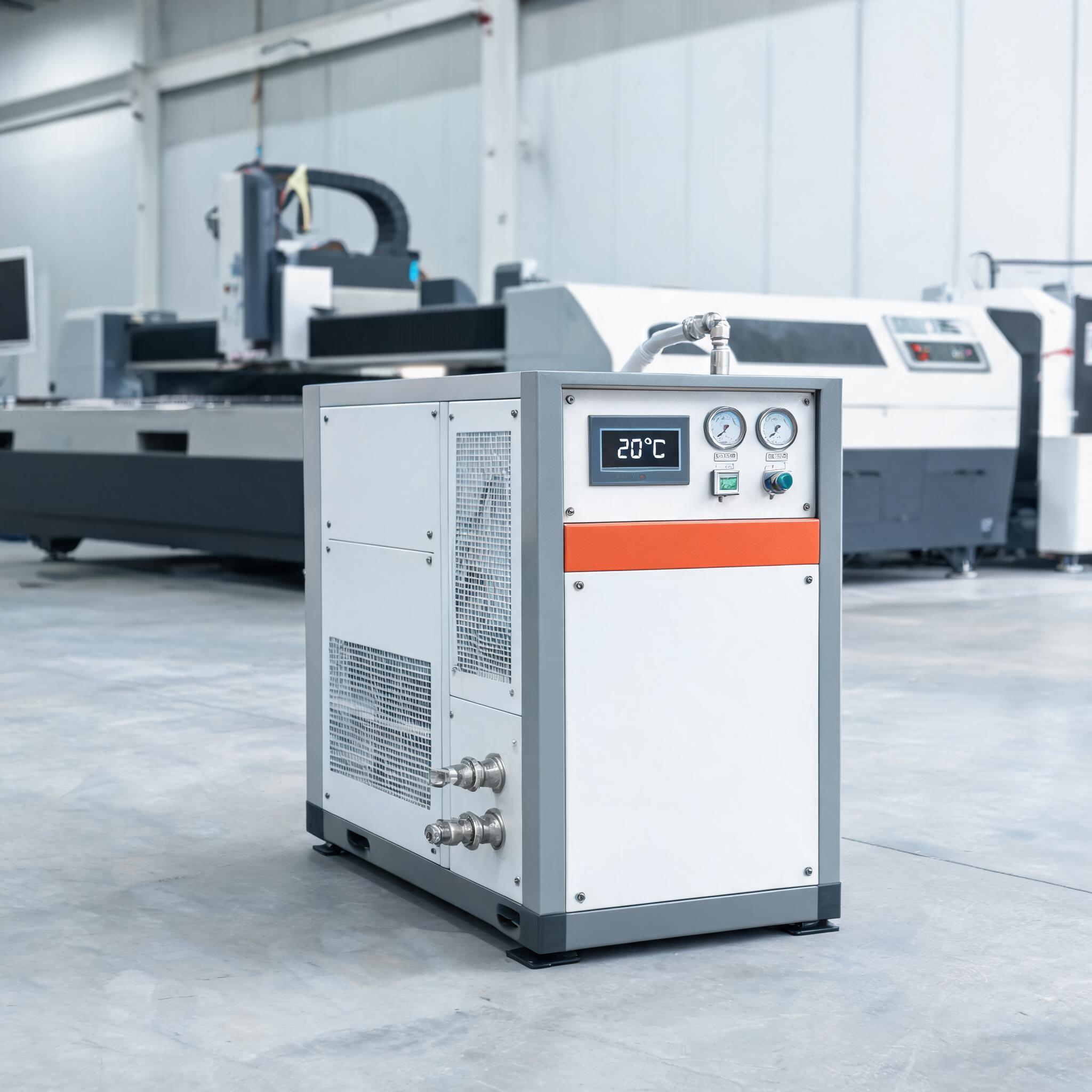
| Cooling system | Laser source needs stable cooling to avoid overheating. | Check chiller water level and temperature. |
Always run a test cut on a small piece of the actual material you will process. Keep a log of parameters that worked—this helps future jobs.
Common Setup Mistakes to Avoid
- Skipping leveling: Leads to inaccurate parts and premature wear.
- Incorrect power phase: Can damage pumps or spindles; always verify phase rotation.
- Not homing the machine: Causes axis position errors and possible crashes.
- Using wrong tool offsets: Results in wrong part dimensions or tool breakage.
- Running a program without dry run: High risk of collision.
- Ignoring laser optics cleaning: Dirty lenses reduce cut quality and power.
Pre-Start Checklist (Printable)
| Item | Status |
|---|---|
| Machine level within tolerance | ☐ |
| Power supply matches specs, phase verified | ☐ |
| Compressed air connected and pressure set | ☐ |
| Coolant filled and concentration correct | ☐ |
| Exhaust connected (for laser) | ☐ |
| Assist gas connected and pressure set (for laser) | ☐ |
| All axes homed successfully | ☐ |
| Tools loaded and offsets entered | ☐ |
| Work zero set correctly | ☐ |
| Program loaded and simulated | ☐ |
| Dry run completed without issues | ☐ |
| Test part produced and measured OK | ☐ |
Final Advice for B2B Buyers
When purchasing a CNC machine, ask the supplier for a detailed installation manual and a recommended spare parts list. Also ask about training—many suppliers offer on-site setup assistance or remote support. A proper CNC machine setup is not just a one-time event; it is the foundation for consistent production quality. If you are setting up a laser cutting machine, pay extra attention to optics and exhaust—they are the most common sources of performance issues.
If you have questions about machine specifications, installation requirements, or need a quote, contact our team. We can provide detailed setup documents and technical support for your project.